This is a brief tutorial of the companion Channelizer Verilog Generation Tool that can be found here . The purpose of the tool is to allow a user to peform the following optimizations.
- Specify channelizer parameters:
- Maximum number of channels.
- Taps per phase.
- Channelizer type (standard M or oversampled M/2 based channelizer
- Specify 6 dB cut-off frequency and transition bandwidths relative to channel/bin width.
- Optimize initial filter.
- Taps are optimized for the specified cut-off and transition bandwidths.
- Verilog Generation
- Tool will generate a downloadable
.zipfile for download.
- Tool will generate a downloadable
The main page is shown below in Figure 1.
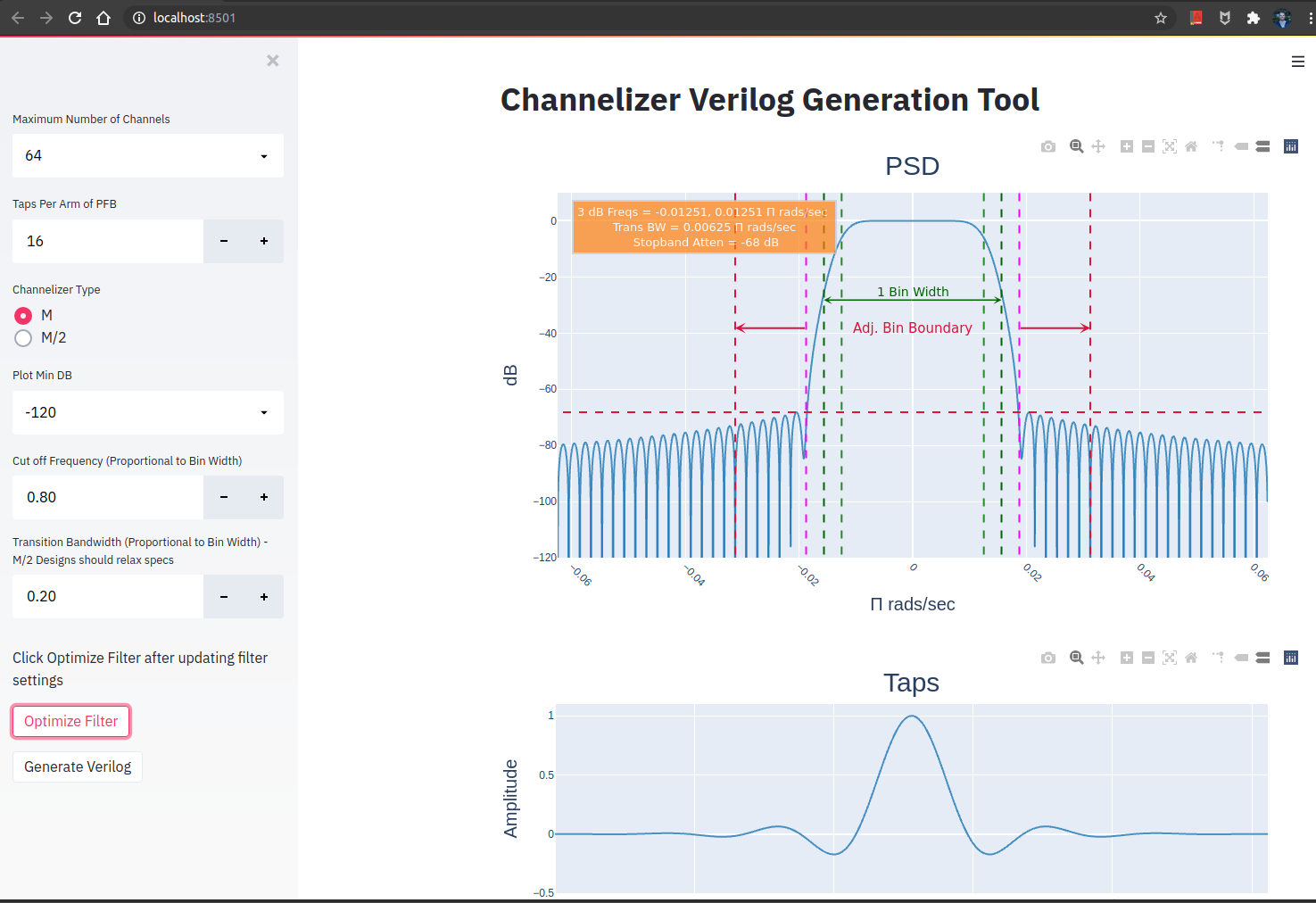
The sidebar on the left is where a user can specify channelizer parameters.
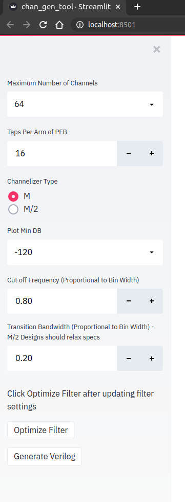
The following table describes the parameters with min / max settings.
| Parameter | Description | Min | Max |
|---|---|---|---|
| Maximum Number of Channels | Max FFT Size (restricted to powers of 2 increments) | 8 | 65536 |
| Taps Per Arm of PFB | Taps per arm of PFB | 12 | 64 |
| Channelizer Type | Select between M or M/2 Channelizer | M | M/2 |
| Plot Min DB | Minimum filter response plot y-axis limit | -280 dB | -60 dB |
| Cut off Frequency | 6 dB cut-off frequency as a ratio of bin width | .5 | 1.0 |
| Transition Bandwidth | filter transition bandwidth as a ratio of bin width | .2 | 1.0 |
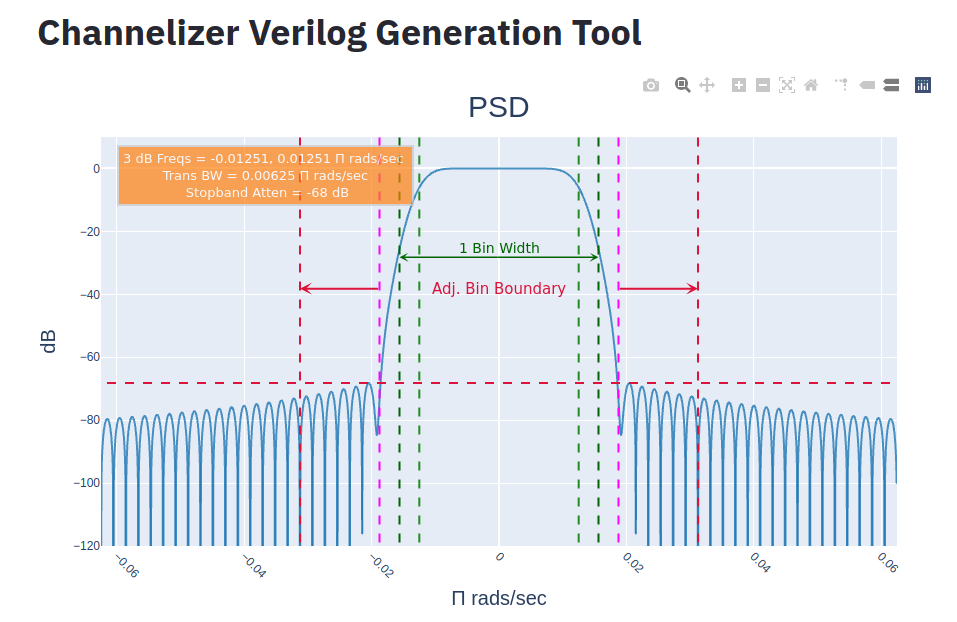
The filter response is shown below in Figure 3. This figure shows the PSD of the currently configured baseband channelizer filter. The light green dashed lines show the current -6 dB cut-off frequency. 6 dB was chosen as it is the cross-over point for perfect reconstruction filters. The dark-green dashed line is the boundary for the for a single bin of the channelizer. The purple lines show the approximate boundary of the transition bandwidth. Finally, the crimson lines show the adjacent bin boundary for \(M/2\) based channelizers. This is the allowable pass-band width including transition bandwidth for \(M/2\) channelizers without suffering excessive adjacent channel aliasing. This is due to the fact that \(M/2\) channelizers downsample by a factor of \(M/2\), not \(M\). All frequency values are given in \(\pi \frac{rads}{sec}\).
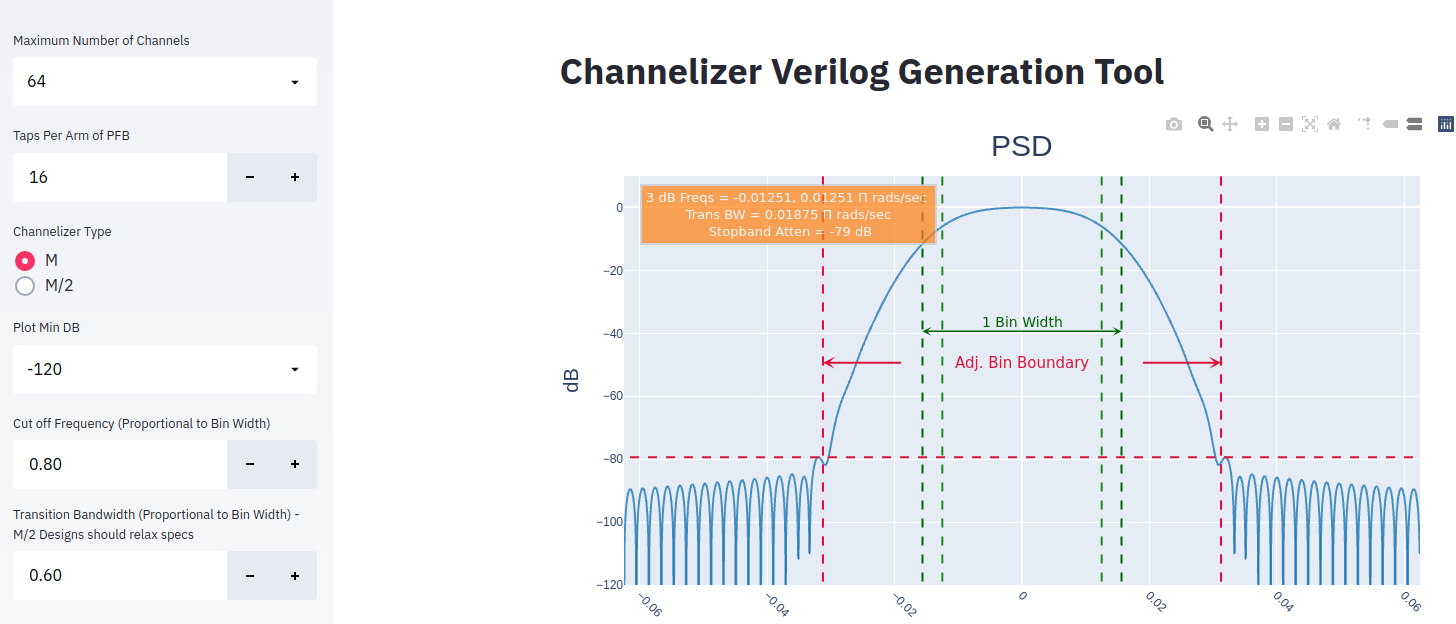
Increasing the transition bandwidth parameter relaxes this filter constraint resulting in much lower stopband suppression as shown below in Figure 4. This new filter was generated by adjusting the Transition Bandwidth setting to .6 and clicking the Optimize Filter button in the sidebar. Note that adjusting the number of channels and/or taps per arm of PFB will automatically result in an updated filter response. Adjusting Cut-off frequency and/or transition bandwidth require the use to click the Optimize Filter button.
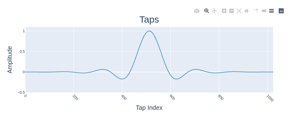
The filter coefficients are shown in the Taps plot as shown in Figure 5.
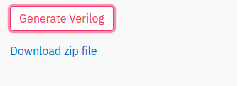
Once a user has configure the channelizer they can then click the Generate Verilog button. The use will be presented with a download dialog box when they click the Download zip file hyperlink.
The table below lists key files along with a description of the file. The files use the following nomenclature. {}Mmax or {}M indicate the maximum FFT size, {}iw is the sample input width (I and Q separately), {}ow is the channelizer sample output width in bits (I and Q separately), {}tps indicates the number of taps per phase in the PFB. Table presents a channelizer with a max FFT size of 64, 16 bit IQ input, 16 bit IQ output, and 16 taps per phase.
| File Name | Description |
|---|---|
| mem_ctrl_pfb_64Mmax_16iw_16ow_16tps.v | Memory controller for Polyphase Filter Bank (PFB). Loads initial coefficients and presents an interface for user to alter coefficients at runtime. |
| pfb_64Mmax_16iw_16ow_16tps.v | PFB logic. |
| xfft_64.xci | Example xfft file. The user will need to use Xilinx tool of choice to generate FFT block with options specified in this file. This example uses a maximum FFT size of 64. |
| chan_top_64M_16iw_16ow_16tps.v | Top level wrapper for the channelizer. |
| chan_top_64M_16iw_16ow_16tps_tb.v | Example testbench for the generated channelizer. |