With the Theseus Cores v1.1.0 release, we now support a highly requested feature for the polyphase channelizer: FPGA-based channel selection and deinterleaving. While I wont go into too much detail on the M/2 polyphase filter bank (PFB) FPGA implementation, I’d like to cover some of the more advanced RFNoC and GNU Radio tricks used here.
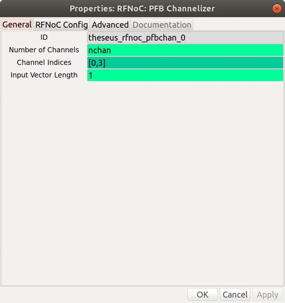
To use the PFB deinterleaving channelizer in GNURadio, we’ve set up the block interface such that the user specifies 1) the total number of equally-spaced channels, and 2) the channel indices to return to software. For example, the following flowgraph implements 64 channels, and then downselects only two of those channels:

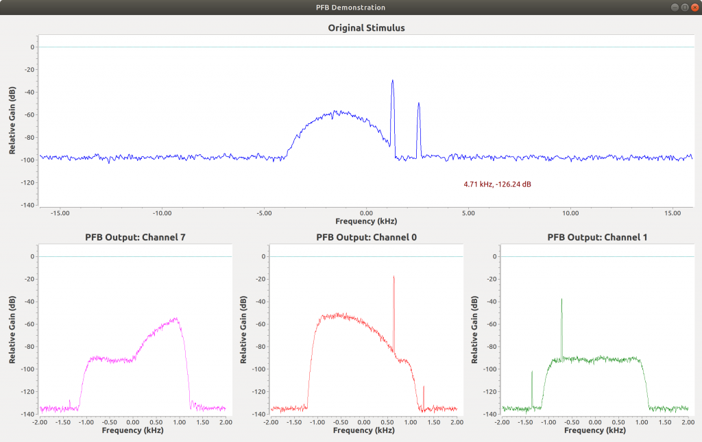
For demo purposes, the two channels extracted are simply indices 0 and 3. Based on the FPGA implementation, channel index 0 refers to the channel centered around 0 Hz, while channel index 1 is the next channel towards more positive frequencies, and so on, wrapping around to the negative frequencies.

Implementation Details
In order to pull this off, we’ve added a few tricks beyond the basic RFNoC, GNURadio, and gr-ettus workflow.
First, a polyphase channelizer typically outputs samples for all N channels fully interleaved by nature of the processing operation. The FPGA implementation downselecting the channels is fairly straightfoward: Using software, write a boolean bitmask to the FPGA indicating whether the channel is active or not. Then, the FPGA indexes into the bitmask and holds the “tvalid” line of the AXI4-Stream interface low if the bitmask is low for each index, effectively blanking out the corresponding output channel. To populate these registers, the PFB block controller accepts a vector of active channel indices, then creates the channel mask and writes registers to the FPGA. Find the relevant PFB controller code here .

Next, to implement software deinterleaving of PFB channels, there’s a few tricky updates needed in the GNURadio block representation. By default, the gr-ettus GNURadio block wrapper is designed to directly reflect the number of ports on the RFNoC FPGA block. However, in the case of the polyphase channelizer, there’s only one output port because data is interleaved onto a single channel; so we essentially need to trick GNURadio and RFNoC by maintaining a single RFNoC port but providing data to GNURadio on an arbitrary number of output ports representing the deinterleaved active channels.
To hack the deinterleaving, the pfbchan GNURadio block overrides the default work_rx_u function in the gr-ettus rfnoc_block_impl.cc (overridden work function here ). The pfbchan GNURadio block saves only a single RFNoC streamer (representing one output port in the FPGA), and there is a single call to recv to gather data. After all the samples are received from UHD, we deinterleaved and copy data to N independent output buffers, and call produce on each channel. We track d_idx as a member variable across work calls, in case RFNoC packet size is not an integer multiple of the number of channels. Here’s a quick snippet from the relevant work function…
    const char *in = (const char *) buff_ptr[0];
    char **outv = (char **) &output_items[0];
    size_t itemsize = output_signature()->sizeof_stream_item(0);
    std::vector<int> produced(nchannels, 0);
    for (int ii = 0; ii < num_samps; ii++){
      memcpy(outv[d_idx], in, itemsize);
      outv[d_idx] += itemsize;
      in += itemsize;
      produced[d_idx]++;
      d_idx++;
      if (d_idx >= nchannels) d_idx = 0;
    }
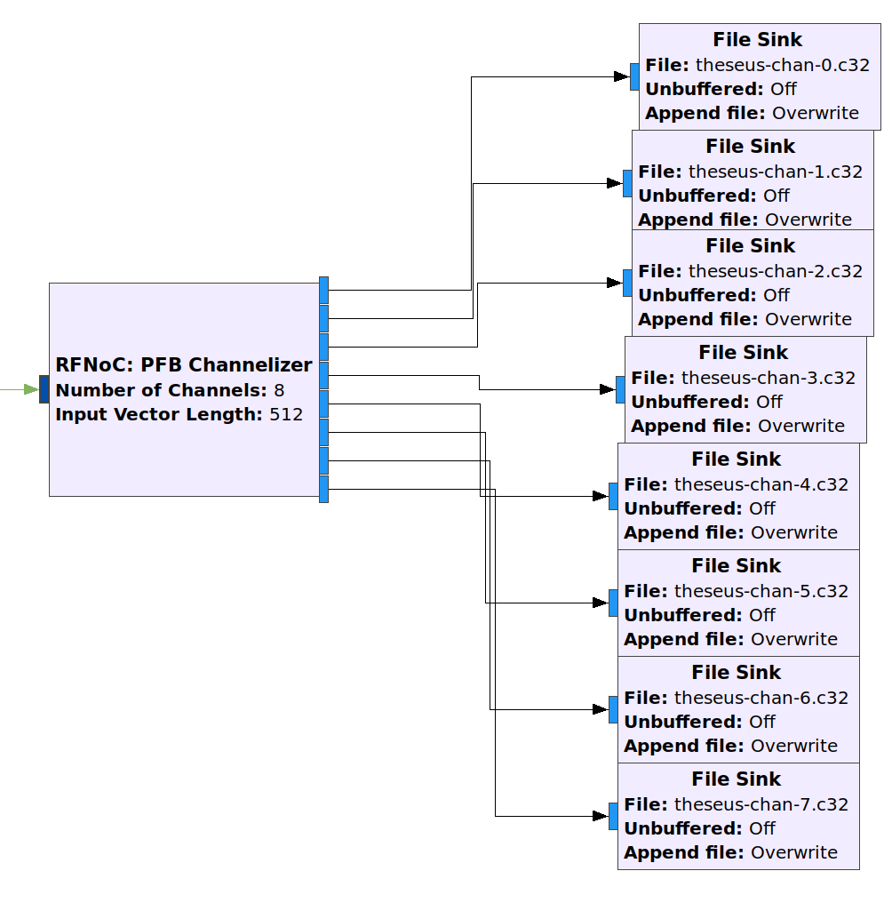
Finally, to make the pfbchan block representation play nice with GNURadio Companion, the output block uses a nports value equal to the number of active channels, and the output is not included in the RFNoC domain. This forces all PFB channelizer output to go into GNURadio software (not another RFNoC FPGA block)… which probably makes sense anyway. The XML definition for the custom PFB block is here . See the following figures for a comparison of plausible block settings.
PFB channel indices range(8):

PFB channel indices [0,1,7]:
![Downselected Channels PFB channel indices [0,1,7]](https://theseus-cores.com/img/2019-12-17-pfb-5.png)
The end result is a GRC block that updates the output ports, configures the FPGA, and deinterleaves the output based on specified block settings! The current M/2 PFB channelizer – compatible with the X310, N3xx, and E320 RFNoC radios – has up to 2048 possible channels with FPGA-based channel selection, which now drastically decreases the transport throughput and CPU overhead required to digitally receive multiple narrowband channels across a wide bandwidth.